Many releases of ammonia occur when handling the nurse tank. Knowledge of the tank will enable responders to control these releases in a quick and safe manner.
- Nurse tanks are used to transport anhydrous ammonia as a liquid under pressure from the dealer to the field.
- Tanks are most often either 1,000 or 1,500 gallons in size although 2000 gallon nurse tanks may be seen.
- A full 1,000 gallon tank will weigh 7,500 pounds and a full 1,500 gallon tank will weigh about 10,600 pounds.
- Nurse tanks are considered full when at 85% of capacity.
- Two 1,000 gallon tanks may be mounted on the same running gear.
All components in contact with ammonia will be constructed of black, mild steel or stainless steel, but never galvanized metals (brass, copper, etc.). All valves and gauges will be located on the top of the nurse tank and toward the front except for the pressure relief valve. The valves and gauges will be protected by a roll cage or some other means. A hydrostatic relief valve will be present anywhere in the plumbing system where ammonia liquid or vapor is trapped and needs to be safely removed.
A slow moving vehicle (SMV) triangle will be attached at the rear of the nurse tank. Safety chains will be used when hooking up. Only one nurse tank unit may be towed full down the road but two units may be towed if each is empty.
There are no pumps on a nurse tank. Liquid flows through an ammonia rated hose to the application toolbar by internal tank pressure. Tanks are painted white or a light color to reflect sunlight keeping the tank shell from heating up. All tanks will have an accessible supply of water for first aid purposes.
 Nurse Tank Markings
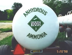
The TDG (Transportation of Dangerous Goods Act) rates anhydrous ammonia as a CLASS 2, Division 2.2 non-flammable, compressed gas. The diamond shaped Department of Transportation pictogram consists of a gas cylinder silhouette above the United Nations identification number 1005 on a green background.
The sides of the bulk tank must also have “Inhalation Hazard” printed in bold letters. For more information on Minnesota labeling and marking requirements see Tank Marking and Placarding Requirements (PDF).
Nurse Tank Anatomy
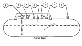
- Liquid Withdrawal Valve
- Liquid Fill Valve
- Pressure Gauge
- Fixed Liquid Level Gauge
- Vapor Return Valve
- Magnetic Float Gauge
- Pressure Relief Valve
Liquid Withdrawal Valve (#1 in diagram)
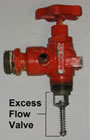
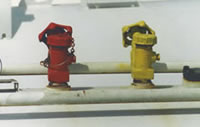
This valve is always positioned at the front of the nurse tank. A dip tube extends from the valve into the tank to the bottom. Internal tank pressure causes liquid to be withdrawn up through the dip tube, through the valve and into an ammonia rated hose to the field application toolbar. Most but not all liquid valves are painted red or orange.
The withdrawal valve contains an internal valve that will safely close when liquid flows out of the tank too quickly. This “excess flow valve” will shut cutting off the flow of ammonia when, for example, a hose ruptures or the withdrawal valve shears off. The excess flow valve will not open again until the withdrawal valve has been closed which allows pressure to equalize on both sides of the excess flow valve seat.
If a nurse tank is tipped on its side, the dip tube will access the vapor space and can not be used to withdrawal liquid ammonia.
Liquid Fill and Vapor Return Valves (#2 and #5 in diagram)
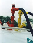 Both the liquid fill and vapor return valves are used to fill a nurse tank from bulk storage. As liquid ammonia is transferred into the nurse tank through the liquid fill valve, vapor moves into the bulk storage tank through the vapor return valve which equalizes the pressures of both tanks.
The liquid fill valve is usually painted red or orange while the vapor return valve will be painted a lighter color typically yellow. Normally they will be installed close together to allow workers quick access to both when filling. The threaded part of the valve will be facing up and have a raincap.
Both the liquid fill valve and the vapor return valve will have an internal excess flow valve that will shut in the event of hose rupture or valve failure during filling.
The liquid fill and vapor return valves do not access the bottom of the tank and therefore cannot be used to off-load an up-righted nurse tank because they access the vapor space only. When the nurse tank is on its side these valves will access liquid and may be used unless the excess flow valves close.
Pressure Gauge (#3 in diagram)
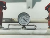
Nurse tanks will have a pressure gauge that reads from 0 to 400 pounds per square inch or psi. Internal tank pressure is affected by ammonia temperature and quantity in tank. Pressures can be as high as 200 psi when liquid ammonia reaches 100°F. (See “Chemical and Physical Properties”)
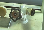
Fixed Liquid Level Gauge and Magnetic Float Gauge (#4 and #6 in diagram)

The fixed liquid level gauge is the small bleeder valve shown at the top of the photo. The gauge has a dip tube that reaches down into the tank to a liquid level of 85%. When opened, vapor will be seen until the liquid level reaches 85% of tank capacity then a small spurt of ammonia liquid will be visible.
The magnetic float gauge (bottom of photo) is a visual indicator of how full the tank is. The gauge reads in percent. Again, nurse tanks should never be filled to greater than 85% full. This allows space in the tank for vapor expansion.
The float gauge will only work on an up-righted nurse tank. Therefore, do not rely upon this gauge when establishing the potential hazard of a release from an overturned nurse tank.
Pressure Relief Valve (#7 in diagram)
To safe guard the integrity of the nurse tank each tank is equipped with a pressure relief valve. This valve accesses the vapor space above the liquid in the tank. If internal tank pressure exceeds 250 psi, the valve will open allowing vapor to escape. This reduces the internal pressure of the tank. Once the pressure drops below 250 the valve will close and the vapor release will stop.
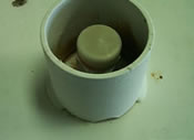
Usually there is some sort of protection around the pressure relief valve. The picture shows a pressure relief valve protected by a metal ring welded to the tank. These valves will have a rain cap to protect it from corrosion.
If a nurse tank is filled to 85% or greater during a cool evening and allowed to warm up during the daytime hours, the pressure within the tank can exceed 250 psi resulting in pressure relief valves opening releasing vapor to reduce tank pressure. This is a normal process. After the pressure decreases to less than 250 psi the valves will close.
Unfortunately, it is not uncommon for valves not to reseat and continue to expel ammonia vapors. In such cases, the nurse tank will need to be offloaded and then the valve can be safely replaced.